ENABLING TECHNOLOGY
FLOWPATH AND HARDWARE
As a result of advances in modern preparative SFC instruments, many of the obstacles associated with preparative SFC have been overcome.⁷ Figure 7 shows the general flow path for Prep SFC instrumentation. SFC uses the same basic flow path as HPLC, including binary pumping and method control, sample introduction to the flow path using injections, column based separations, peak detection, and fraction collection. In SFC, there are additional technologies required, mostly to handle the compressibility and expansion of CO2. These include heat exchangers (HE), back pressure regulators (BPR), gas liquid separators (GLS), and the almost universal use of high pressure stainless steel tubing.
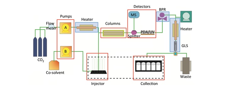
Figure 7. General SFC flow path highlighting similarities in red (Pumps, Injector, Columns, Detectors, Collection) and differences in blue (Heaters, Back Pressure Regulator (BPR), and Gas Liquid Separator (GLS)). (This diagram shows the plumbing setup typically used with modifier-stream injection and open bed collection).
Considerations for each component will be discussed below:
Pumping: In SFC, as in LC, binary pumping systems are used to deliver an “A” solvent, in this case always CO2, and a “B” solvent, typically a polar organic solvent like methanol. Depending on the scale of the system, the CO2 is delivered two ways, either volumetrically (volume flow), which is typical at the analytical scale, or by mass (mass flow), as is often done at the prep scale. Because CO2 is compressible, identical volumes do not necessarily equate to identical mass because of differences in density. Either delivery method is valuable as long as the flow rates are reproducible, independent of the environmental conditions. In most cases, the CO2 is chilled either before the pump or within the pump heads, and then pumped as a liquid to reduce any discrepancy in the mobile phase density. In addition, all seals, check valves, tubing and fittings need to be able to handle a high pressure compressible fluid without leaking. Because the CO2 easily expands through any opening, even a small leak can have a large impact on system performance and chromatography. Poor pumping of the CO2, whether due to tubing leaks, seals, or check valves can result not only changes in retention time and selectivity, but also poor pressure (density) control and baseline noise.
Injections: There are two commonly used injection modes, mixed-stream and modifier stream that will be discussed in detail in the “Injection strategies in SFC” section. Mixed-stream SFC injection schemes involve a depressurization step, used to vent any CO2 from the loop prior to loading sample. Depressurization is also sometimes used in systems that do both mixed-stream and modifier-stream injections as a safety precaution. Usually, this is done with a secondary “vent” valve. One drawback to this setup is extra-column volume added to the system during the injection, which can lead to peak broadening and a loss in resolution. By keeping the volume to a minimum using small ID tubing, the peak broadening is reduced.
Column Oven and Heating: In SFC, pressure and temperature are method parameters that impact the separation because they affect mobile phase density. As a result, proper heating and temperature control of the mobile phase and column are necessary. If the temperature is not properly controlled, temperature gradients that occur in the column can have detrimental effects on peak shape and resolution. In many SFC systems this is accomplished by either heating the column in an oven, or by pre-heating the mobile phase, or both.
Identifying the right column chemistry (both chiral and achiral) is critical in SFC. Column screening is therefore required in SFC applications.⁷ Many SFC systems are equipped with some type of switching valve included in the oven to choose between multiple columns. This is particularly important in applications where many different samples and targets are being purified that likely require different column chemistries.
Detectors: All of the typical detection techniques used in purification such as UV/Vis, PDA, MS and ELS are compatible with SFC, and multiple detectors can be used within a single system. Typically, the UV/Vis and PDA detectors are plumbed in the main flow path because they are non-destructive detectors and are used for primary detection. The flow cells for these detectors need to be rated appropriately for the pressures used in SFC. Destructive detectors, such as the MS and ELS, are plumbed using splitter technology that has relative control of the split ratio and conditions the solvent to optimize the detection signal. Multiple detector signals (or channels) can be logged or used for fraction triggering, expanding the application range of the technology for both analytical and preparative SFC. The use of these detectors in SFC is covered in more detail in the “Optical and MS Detection in SFC” section of this chapter.
Back Pressure Regulator (BPR): Controlling the density of the mobile phase along the column is one of the most important factors in SFC instrument design because solubility and retention factor of all compounds are closely related to the fluid density. Density control is accomplished primarily by controlling the pressure within the system. The back pressure regulator is an automated device designed to control the post column pressure (back pressure) of the system at a pressure specified within the method. To acquire suitable, repeatable chromatography, the post column pressure has to remain constant (at the set point) even under gradient conditions and run-to-run.
Even though CO2 is considered supercritical above 74 bar (~1073 psi) and 31°C, it is typically not recommended to run at conditions close to the critical point because small changes in temperature or pressure in this region result in large changes in density.⁵ As a result, methods developed in this region would be less robust in terms of retention and resolution. Also, when co-solvents are being used, phase separation is more likely at low pressure conditions resulting in baseline noise. Therefore, most SFC methods use higher pressure set points, typically greater than 100 bar (1450 psi).
Collection Triggers: In Prep SFC, collections can be triggered on multiple channels and detectors using threshold, time and slope collection modes (defined in table 3). Boolean logic is used for more intelligent collection, requiring more than one condition to be met before collection occurs. The conditions for collection can include combinations of modes, like threshold and time, or combinations of detector signals, like a UV threshold and mass confirmation.
|
Collection mode
|
Description
|
|
Threshold
|
Collection occurs above a specified signal intensity (height)
|
|
Time
|
Collection occurs during a specified start and stop time (forced collection) regardless of signal
|
|
Slope (or derivative)
|
Collection occurs when the change in the signal (slope) meets a specified value or percentage
|
Table 3. Definitions of collection modes used in preparative SFC.
Collection timing delay is also important and proper delays between the detector and collection system must be determined for optimal recovery of target compounds. Just as in Prep HPLC, these delays are dependent on flow rates. In SFC, however, changes in collection timing also accompany changes in mobile phase composition and pressure. With the use of make-up solvents, and other technologies to mitigate the CO2 expansion, the timing can be better controlled across a range of conditions at a set flow rate.
INJECTION STRATEGIES IN SFC
Preparative separations require the introduction of large amounts of material onto the separation column. Typically, it is ideal for the sample diluent to match the mobile phase or mimic the mobile phase polarity in order to minimize peak broadening and distortion. In SFC, this is impractical because of the difficulty in handling CO2 under liquid conditions. Two previous strategies have been attempted to match the sample diluent to the SFC mobile phase. The first involved trapping the sample on a pre-column, removing the diluent with a neutral gas (usually nitrogen) and then sweeping the sample onto the column with mobile phase. The second strategy involved coupling SFE (extraction) directly with Prep SFC. Both strategies improved sample loading, however they were too time consuming to improve overall productivity.⁶
Currently, there are two approaches to sample injection in SFC applications: mixed- stream and modifier-stream (diagrams in Figure 8). In mixed-stream injection, the entire mobile phase (CO2 and co-solvent) sweep the loop and carry the sample to the column. Common issues with mixed-stream injection are peak distortion and retention time shifts caused by strong diluent effects. Standard practice is to dissolve the sample in the polar modifier (co-solvent). Use of a strong solvent like methanol causes some of the analyte not to be absorbed on the stationary phase, resulting in peak breakthrough or distortion. For peaks that are less retained, there is a greater impact and the distortion becomes more severe.⁶ As the injection volume increases, the slug of polar solvent causes localized disturbance in the mobile phase, distorting peaks even further while also decreasing resolution. This injection strategy also requires depressurization, which can have an impact on injection loading and repeatability. With mixed-stream injection, diluents with similar polarity to the CO2 (such as hexane, heptane, or other non-polar solvents) have been shown to improve peak shape (Figure 9).
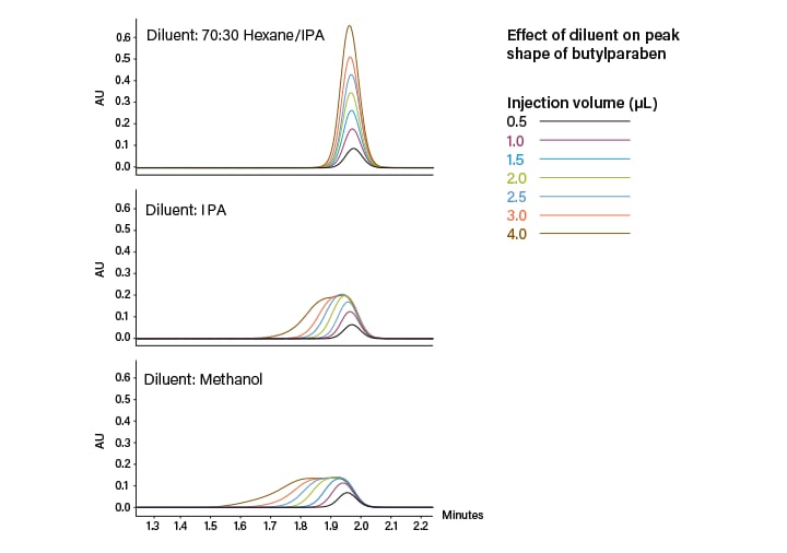
Figure 9. Effect of sample diluent strength on peak shape using mixed-stream injections in SFC.
The second injection strategy is modifier-stream injection, where the sample is injected into the organic portion of the mobile phase (co-solvent) prior to mixing with CO2. This is similar to the at-column dilution schemes used in LC purification. The idea is to mitigate the diluent affect by introducing the sample without affecting the overall strength of the mobile phase, and maintaining the programmed solvent percentages throughout the injection and run. In this case, the diluent should match the co-solvent being used for the separation; however, other diluents can be used. Modifier-stream injection provides improved peak shape and resolution, allowing for larger injection volumes and higher loading (Figure 10).
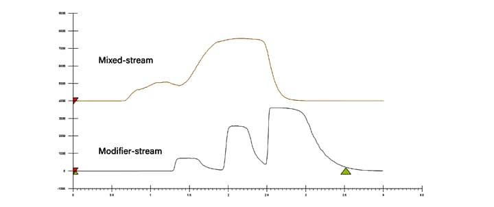
When using modifier-stream injection at low co-solvent percentages, the time to apply the sample to the head of the column is increased due to the low flow rate of the co-solvent pump. Because of the highly diffusive mobile phase, it is possible the increased injection time could result in broader peaks, as compared to mixed-stream injections. However, the peak shape is still improved when compared to high volume mixed-stream injections at low co-solvent percentages. Even though mixed-stream transfers the sample to the column faster, the magnitude of the disturbance under these conditions overwhelms any benefit. As the co-solvent percentage increases, the choice of injection technique becomes less critical, but at low co-solvent percentages modifier- stream is significantly better.⁶
Figure 10. 2 mL injections (40mg loading) of flavor compounds using mixed-stream (top) and modifier-stream (bottom) injection techniques at 10% co-solvent method conditions.
OPTICAL AND MS DETECTION IN SFC
PDA and UV/Vis Detection
There are SFC specific considerations when it comes to optical detection in SFC. Changes in mobile-phase density and differences in refractive indices between CO2 and the co-solvent create baseline drift and noise in UV/Vis and PDA detectors (Figure 11). These effects are especially pronounced under gradient conditions. In the PDA detectors, the baseline can be adjusted using single wavelength channels and wavelength compensation that reduces baseline noise and increases sensitivity (Figure 12). In UV/Vis detectors, setting a single wavelength makes the baseline noise and drift less pronounced.
From a hardware standpoint, specific flow cells have been designed to handle the high pressures of SFC applications and can be used in Waters 2998 PDA and 2489 UV/Vis detectors. Flow cell design properties including path length, geometry, and cell material have been studied to optimize detection in SFC applications.
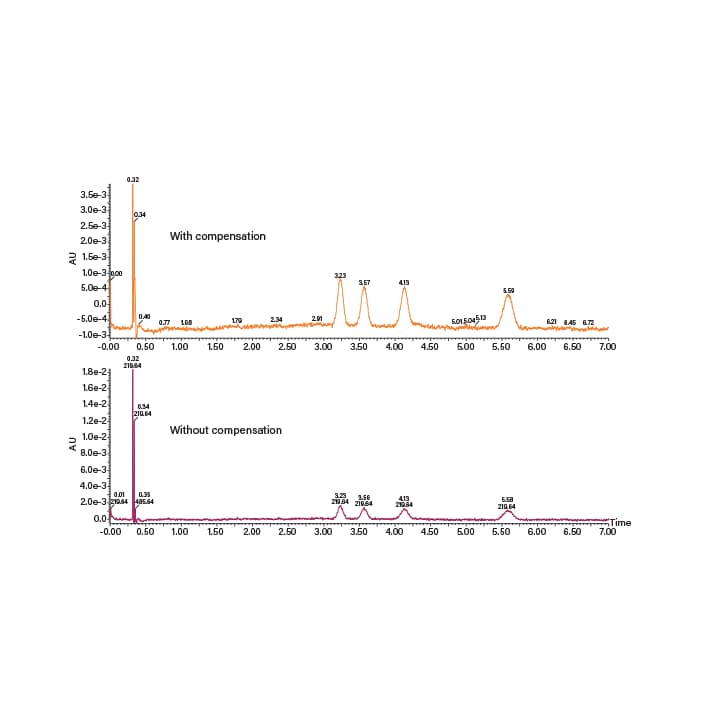
Figure 12. Chromatograms acquired using a PDA detector with (top) and without (bottom) utilizing wavelength compensation for low level detection.
MS Detection
One of the great advantages of SFC is the ability to pair normal-phase selectivity with MS compatibility. The CO2 in SFC not only replaces non-compatible solvents like hexanes and heptanes, but also, through gas expansion, aids in nebulization and particle formation within the MS source. SFC is compatible with ESI, APCI, and dual mode acquisition in a wide range of MS instruments. The Waters ACQUITY QDa® Detector is particularly useful in Prep SFC because it is easy to use. However, at low co-solvent percentages there are often not enough ions present for optimal signal detection. Because of this, a conditioning solvent (or make-up solvent) is usually added at the split to boost signal in the MS. A typical conditioning solvent contains a mixture of methanol, water and an additive (often ammonium hydroxide or formic acid). Many other conditioning solvent mixes are used, at a range of flow rates, depending on the preferences of the user, the type of MS instrument, and the scale of the application. Examples of MS-ESI detection on a Waters ACQUITY QDa Detector with and without the conditioning solvent can be seen in Figure 13.
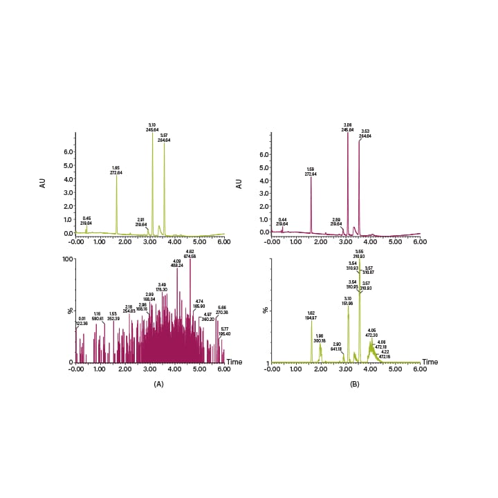
Figure 13. Chromatograms showing MS detection in SFC. The top chromatograms are the UV traces, the bottom ones are (A) QDa-MS signal without conditioning solvent, and (B) QDa-MS signal with 95:5:20mM methanol/water/ammonium hydroxide conditioning solvent at 0.6 mL/min.
ELS Detection
SFC is compatible with ELS detection as well. Just like with MS, a split is used, and make-up solvent is added to improve signal. Because the SFC mobile phase is so volatile, the extra solvent is required to carry the sample and obtain better signal in the ELS detector. Operationally, the ELSD is controlled similarly for SFC as it is for LC.
COLLECTION IN PREP SFC: CO2 EXPANSION CONSIDERATIONS
The properties of an expanding mobile phase are important when considering collection control in Prep SFC. At the critical point, 31°C and 74 bar, the volumetric expansion
of pure CO2 to atmospheric conditions (1 bar and 15°C) is approximately 250 times.
In preparative SFC systems, high pressure CO2 exits at the back pressure regulator (BPR). This volumetric expansion increases exponentially, as the pressure of the exiting CO2 increases. In binary systems, like the typical SFC mobile phase, the expansion decreases as the CO2 fraction decreases and the organic portion increases.13 As expansion occurs, the dissolution capacity of the mobile phase is reduced, both by the lack of solvating power and Joule-Thomson cooling. The cooling can also cause dry ice formation that can block tubing. A lack of expansion control can cause peak distortion in the collection flow path, reducing fraction purity. It can also result in a loss of recovery, as the target compounds are swept out to waste, or are lost through vaporization at the collection point.
To successfully collect fractions, there are many strategies utilized in SFC instrumentation to control CO2 expansion and its effects. First, in order to mitigate the cooling and associated issues, the mobile phase is heated at the initial expansion point, right after the back pressure regulator. Second, in many cases an organic make-up solvent is added, which not only keeps the compounds in solution, but also helps to control expansion by lowering the volumetric fraction of CO2. Having better control of the expansion, improves post BPR peak shapes, and improves recovery. Finally, the CO2 is vented or removed. Typically some kind of phase separation device is used for this purpose, such as high pressure cyclones or gas-liquid separators (GLS) (Figure 14).
High pressure cyclones push the heavier (liquid) portion of the mobile phase to the outside and bottom of the cyclone while allowing the CO2 gas to escape out the center and the top. Advantageously, high pressure cyclones require no make-up solvent (even at lower co-solvent percentages) because the solvating power of the CO2 is maintained through the collection valve, and phase separation occurs in the cyclones. However, there are several disadvantages as well. High pressure collection systems require high pressure materials, like stainless steel, and are an increased safety risk due to the spray and expansion associated with recovering fractions. These systems also restrict the user to a limited number of positions available for collection in a “closed-bed” format. The gas-liquid separator (GLS) is an alternative, low pressure option that has many advantages. Low pressure systems allow the use of lower pressure rated materials, and have a significantly reduced safety risk. And although additional solvent is typically required for collection, the more complete removal of CO2 under low pressure conditions makes open-bed collection a reality, considerably increasing the number of fractions that can be collected and expanding the applicability of the technology.
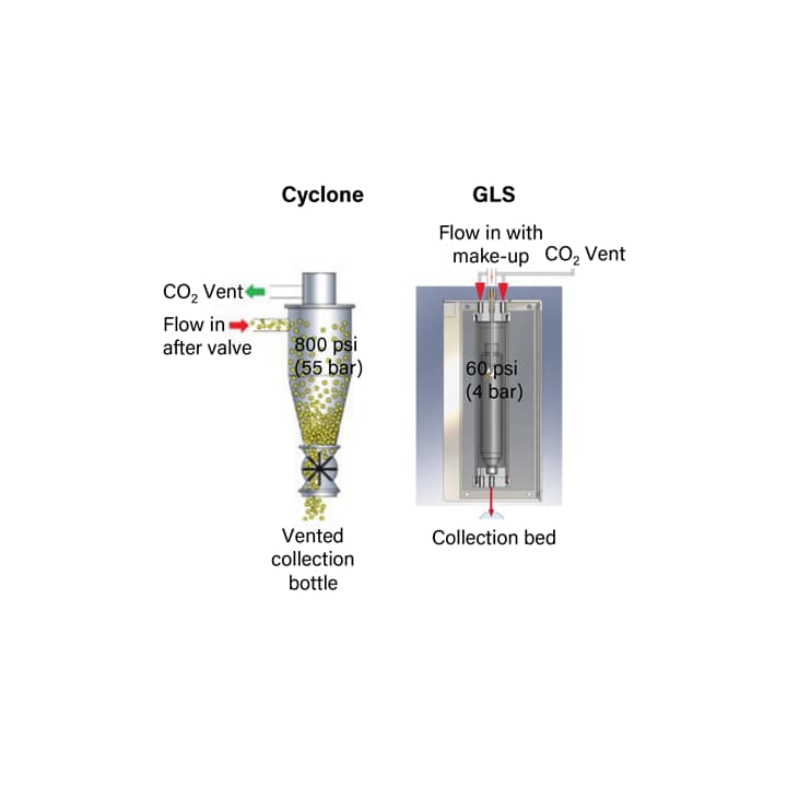
Figure 14. Schematics for the high pressure cyclone and gas liquid separator used to separate and remove the CO2 during collection in preparative SFC.
DIVERSE SELECTIVITY AND APPLICABILITY
Prep SFC provides an exceptional increase in selectivity to the purification process. While SFC generally utilizes normal-phase separation, the technique is incredibly flexible because it allows the use of some conventional RPLC columns, and solvents, extending the range of compound compatibility. The ability to span this wide range of selectivity is a clear SFC advantage because it provides orthogonal separation within a single platform, streamlining the entire purification process.
SFC COMPATIBILITY: SOLUBILITY
SFC operates, at a basic level, under a normal-phase chromatographic separation mode.10 Under typical running conditions, the majority of the mobile-phase is non-polar CO2 paired with a small fraction of polar organic solvent, and the separation occurs on small particle packed columns containing relatively polar stationary phases of wide ranging functionality. Because of the low mobile phase viscosity, and small particle columns, SFC is primarily used in small molecule applications. However, the range of higher molecular weight applications done using SFC is continuously expanding. Otherwise, a compound’s candidacy for SFC is mostly dependent on solubility. SFC has an extremely wide range of solubility. In fact, as a general rule, any sample that can be dissolved in an organic solvent is a candidate for SFC. This is very useful, because many sample preparation techniques result in samples dissolved in organic solvents, which can be directly injected onto the Prep SFC instruments.
One useful piece of information regarding the solubility of a compound in organic solvents relates to the partition coefficient, usually designated as LogP. Generally, the LogP is a measure of the lipophilicity or hydrophobicity of a compound. Specifically, it is the ratio of concentration of a compound in the two phases of a mixture of two immiscible solvents at equilibrium; usually water and 1-octanol (Figure 15).14 Because CO2 is a non-polar solvent, LogP values are a good indicator of how a compound will behave under SFC conditions. Low LogP values indicate higher polarity, the result of which is less solubility in CO2 and more affinity for the polar column chemistries, while high LogP values indicate low polarity resulting in more CO2 solubility and less affinity for the column. The opposite of this is true in RPLC, where the mobile phase is polar and the stationary phase is non-polar.
In analytical (UPC2) applications, lower loading and less concentrated samples can accommodate compounds with LogP values between -2 and 9. In preparative SFC, however it is important that compounds stay in solution when introduced to CO2 under high loading conditions. Samples that contain very polar or hydrophilic compounds at preparative concentrations and amounts should be tested for solubility, prior to injection on the system. This is typically done by dissolving the sample in a suitable organic solvent, followed by introducing a small amount of hexane or heptane. If the sample precipitates out of solution it is generally considered not suitable for preparative SFC.
One disadvantage of Prep SFC is the poor solubility of highly polar compounds. However, with the addition of a small amount of water (as an additive, usually less than 5% v:v) to the organic portion of the mobile phase, SFC can be used for an even broader range of sample polarity. The water increases the solubility of hydrophilic compounds, making separation and purification of those compounds possible. The scope of SFC applicability can, therefore, be extended to the study of peptides, proteins, nucleobases, and other hydrophilic analytes.10 While this technique has been proven to aid in polar applications, it should be approached with caution in preparative SFC to avoid sample precipitation or ice formation at the system outlet.
SFC APPLICABILITY: CO-SOLVENTS
Co-solvent selection is a key parameter in SFC for chromatographic method development and optimization. In both normal and reversed-phase liquid chromatography, there are restrictions on solvent miscibility. The aliphatic hydrocarbons in normal-phase, and water in reversed-phase, limit the polarity range of solvents that can be used in those separations. In SFC, supercritical CO2 is miscible with both reversed-phase and normal-phase organic solvents, from methanol to heptanes opening up a wide range of solvent selectivity choices to develop a separation (Table 4). This wide range of selectivity greatly increases the range of SFC compatible applications.
Table 4. List of solvents and their respective compatibility with NPLC, RPLC and SFC
SFC APPLICABILITY: COLUMNS
In reversed-phase chromatography most separations are performed on a limited number of stationary phases, typically C18 or similar hydrophobic columns. A wide variety of chiral and achiral column chemistries that span both the reversed-phase (non-polar) and normal-phase (polar) range are applicable in SFC (Table 5). Basic, neutral and acidic compounds are well eluted on most columns, indicating the suitability of Prep SFC for a broad range of chemical functionalities.⁷ Use of a variety of columns can be seen as a disadvantage; however, it is also an opportunity to optimize selectivity to purify a particular compound.⁷ Modern Prep SFC stationary phases provide additional potential for increased use of SFC for chiral and achiral purification.³ In particular, Waters Viridis and Torus columns are specifically designed for the SFC application, offering better stability, a wide range of selectivity, and better peak shape; reducing the need for additives. Table 6 shows a list of Waters columns that cover the range of Prep SFC applicability. Column selection is a key parameter in method
development and optimization.
Table 5. List of achiral and chiral columns and their typical compatibility with NPLC, RPLC, and SFC.
|
Viridis (achiral)
|
Torus (achiral)
|
Trefoil (chiral)
|
|
Silica/BEH
|
2-PIC (2-picolylamine)
|
AMY 1 (amylose)
|
|
BEH 2-ethylpyridine
|
DEA (diethylamine)
|
CEL 1 (cellulose)
|
|
Silica 2-ethylpyridine
|
Diol (high density diol)
|
CEL 2 (cellulose)
|
|
CSH flouro-phenyl
|
1-AA (aminoanthracene)
|
|
Table 6. Waters stationary phases covering the application range of SFC.
CHIRAL SEPARATION
SFC is, by far, the best chromatographic solution for separating chiral compounds, providing considerable improvements in separation efficiency and speed as compared to other chromatographic techniques, such as normal-phase HPLC. Chiral separations are typically achieved using normal-phase HPLC. In SFC these separations are
done in significantly less time, while also increasing resolution and reducing solvent consumption. Chiral columns are, therefore, heavily used in the SFC environment, not only for chiral applications, but also for the separation of diastereomers, metabolites, regioisomers, and other structurally related compounds.⁷ While the cellulose and amylose based phases are the most popular, other chiral stationary phases are compatible as well. This has advantages in purification of these compounds such as higher purity fractions, higher efficiency, and cost savings due to a reduction in solvent usage. Figure 16 shows the chiral separation of the enantiomers and diastereomers
of permethrin using both normal-phase HPLC and SFC. All four peaks could not be resolved using HPLC; however they were resolved in less time and using a shorter column using SFC.15
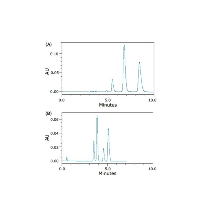
Figure 16. Chromatograms of the separation of the stereoisomers of permethrin obtained under normal-phase HPLC (A) and SFC (B) conditions.15